Principles of Operation for Ceramic Resonators
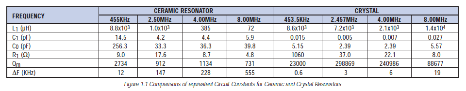
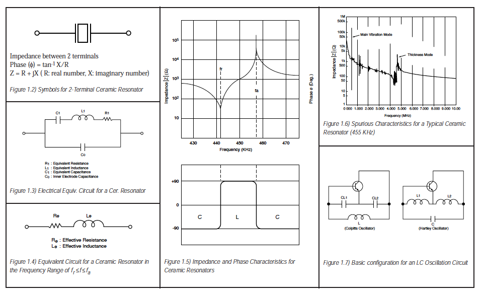
Equivalent Circuit Constants: Fig.1.2 shows the symbol for a ceramic resonator. The impedance and phase characteristics measured between the terminals are shown in Fig.1.5. This figure illustrates that the resonator becomes inductive in the frequency range between the frequency fr (resonant frequency), which provides the minimum impedance, and the frequency fa (anti-resonant frequency), which provides the maximum impedance. It becomes capacitative in other frequency ranges. This means that the mechanical oscillation of a two-terminal resonator can be replaced with an equivalent circuit consisting of a combination of series and parallel resonant circuits with an inductor L, a capacitor C, and a resistor R. In the vicinity of the resonant frequency, the equivalent circuit can be expressed as shown in Fig.1.4. The fr and fa frequencies are determined by the piezoelectric ceramic material and its physical parameters. The equivalent circuit constants can be determined from the following formulas:
Considering the limited frequency range of fr<f<fa, the impedance is given as Z=Re+jwLe (Le<=0) as shown in Fig.1.5. The ceramic resonator should operate as an inductor Le (H) having the loss Re (). Fig 1.1 shows comparisons for equivalent circuit constants between a ceramic resonator and a quartz crystal resonator. Note there is a large difference in capacitance and Qm which results in the difference of oscillating conditions when actually operated. The table in the appendix shows the standard values of equivalent circuit constants for each type of ceramic resonator. Higher harmonics for other modes of oscillation exist other than the desired oscillation mode. These other oscillation modes exist because the ceramic resonator uses mechanical resonance. Fig.1.6 shows these characteristics.
Basic Oscillating Circuits
Generally, the oscillating circuits can be grouped into the following three types:
- Positive feedback
- Negative resistance element
- Delay of transfer time or phase in the case of ceramic resonators, quartz crystal resonators, and LC oscillators, positive feedback is the circuit of choice.
Among the positive feedback oscillation circuits using LC, the tuning type anti-coupling oscillation circuit, by Colpitts and Hartley, are typically used. See Fig. 1.7.
In Fig.1.7 a transistor, which is the most basic amplifier, is used.
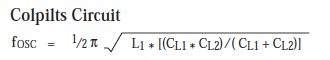
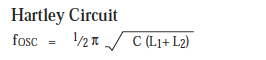
The oscillation frequencies are approximately the same as the resonance frequency of the circuit consisting of L, CL1, and Cl2 in the Colpitts circuit or consisting of L1, L2, and C in the Hartley circuit. These frequencies can be represented by the following formulas.
In a ceramic resonator oscillator, the inductor is replaced by a ceramic resonator, taking advantage of the fact that the resonator becomes inductive between resonant and anti-resonant frequencies. The most commonly used circuit is the Colpitts circuit.
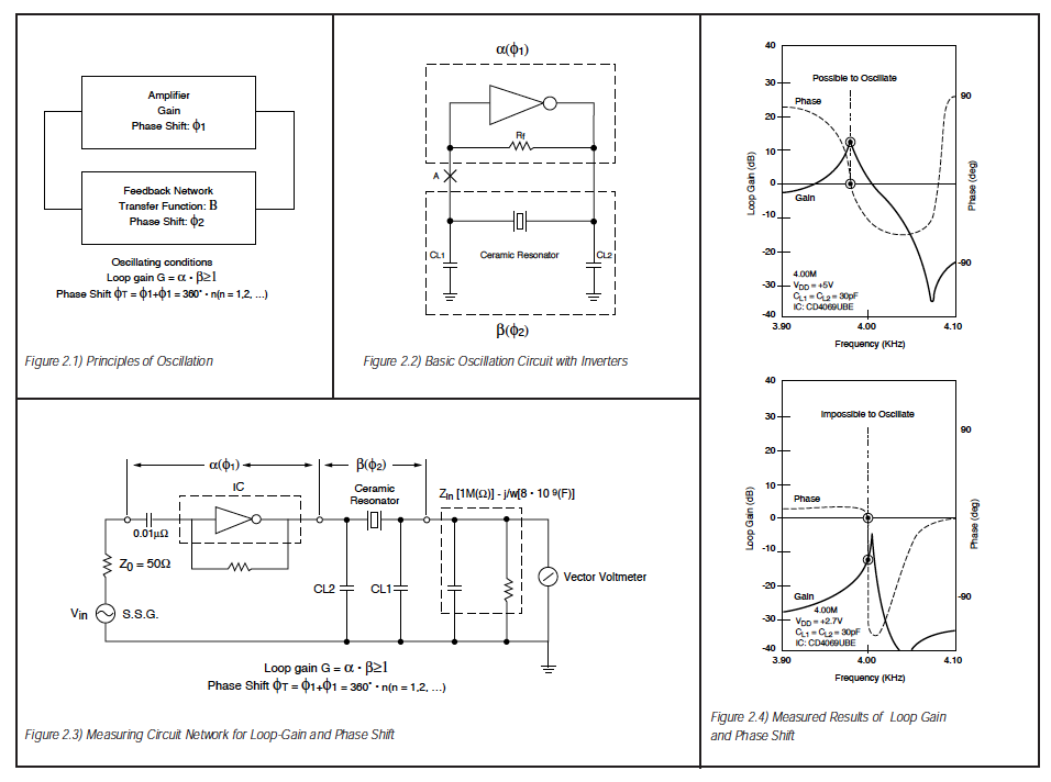
The operating principle of these oscillation circuits can be seen in Fig.2.1. Oscillation occurs when the followin conditions are satisfied. Loop Gain: G= a : B> 1 Phase amount:
In a Colpitts circuit, an inversion of 180 is used, and it is inverted more than =180 with L and C in the feedback circuit. The operation with a ceramic resonator can be considered as the same.
Applications
Typical Oscillation Circuit: The most common oscillator circuit for a ceramic resonator is a Colpitts circuit. The design of the circuit varies with the application and the IC to be used, etc. Although the basic configurations of the circuit is the same as that of a crystal controlled oscillator, the difference in mechanical Q results from a difference in circuit constants. Some typical examples follow.
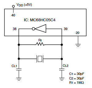
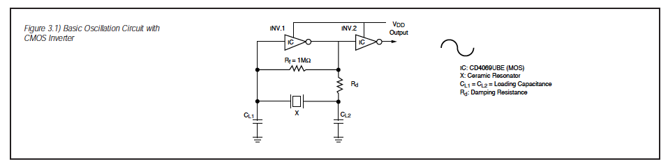
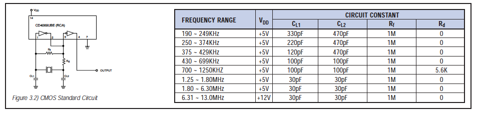
Design Considerations: It is becoming more common to configure the oscillation circuit with a digital IC, using an inverter gate. Fig.3.1 on the following page shows the configuration of a basic oscillation circuit with a CMOS inverter. INV.1 operates as an inverting amplifier for the oscillating circuit. INV.2 is used as a waveform shaper and also acts as a buffer for the output. The feedback resistance Rf provides negative feedback around the inverter so that oscillation will start when power is applied. If the value of Rf is too large and the insulation resistance of the input inverter is too low, then oscillation will stop due to the loss of loop gain. Also, if Rf is too great, noise from other circuits can be introduced into the oscillation circuit. Obviously, if Rf of 1M is generally used with a ceramic resonator. Damping resistor Rd has the following function although it is sometimes omitted. It makes the coupling between the inverter and the feedback circuit loose; thereby decreasing the load on the output side of the inverter. In addition, the phase of the feedback circuit is stabilized. It also provides a means of reducing the gain at higher frequencies, thus preventing the possibility of spurious oscillation.
Loading Capacitance: Load capacitance CL1 and CL2 provides a phase lag of 180. These values should be properly selected depending on the application, the IC used, and the frequency. If CL1 and CL2 are lower values than necessary, the loop gain at high frequencies is increased, which in turn increases the probability of spurious oscillation. This is particularly likely around 4-5MHz where the thickness vibration mode lies.

This clearly shows that the oscillation frequency is influenced by the loading capacitance. Caution should be taken in defining its value when a tight tolerance for oscillation frequency is required.
CMOS Inverter: A CMOS inverter can be used as the inverting amplifier, the one-stage type of the 4069 CMOS group is the most useful. Because of the excessive gain, ring oscillation or CR oscillation is a typical problem when using the three-stage buffer type inverterm such as the 4049 group. ECS employs the RCA CD4O69UBE as a CMOS standard circuit, as shown in Fig.3.2.
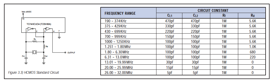
HCMOS Inverter Circuit: Recently, the high speed CMOS (HCMOS) is increasingly being used for circuits allowing high speed and low power consumption for microprocessors. There are two types if HCMOS inverters: the un-buffered 74HCU series and the 74HC series with buffers. The 74HCU system is optimum for ceramic resonators. See Fig.3.3.
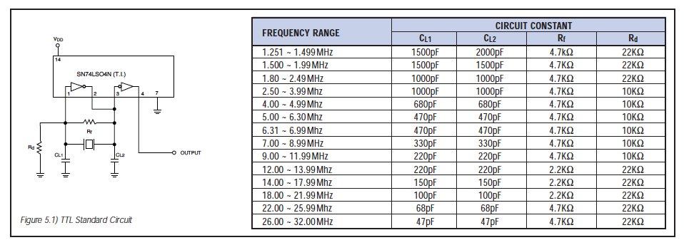
TTL Inverter Circuit: The value of load capacitance CL1 and CL2 should be greater than those of CMOS due to impedance matching. In addition, the feedback resistance Rf should be as small as several K. Note that the bias resistance Rd is required to properly determine the DC operating point.
Frequency Correlation: The oscillator circuits shown on the following page are ECS standard test circuits. The inverters used in these circuits are widely accepted as the industry standard because their characteristics are representative of those found in microprocessors within the same family (CMOS/HCMOS/TTL). Naturally, applications will differ in what IC is used, and as can be expected, oscillator circuit characteristics will vary from IC to IC. Usually, this variation is negligible and a ceramic resonator part number can be selected simply by classifying the processor as CMOS, HCMOS or TTL. Given that the standard ECS ceramic resonators are 100% frequency sorted to the test circuits on the following page, it is relatively easy to correlate the frequency of oscillation of our standard circuit that of a customer specified circuit. For example, if the microprocessor being used is a Motorola 6805 at a frequency of 4MHz, then the correct ECS part number would be ZTA4.OMG (frequency sorted to the CD4O69UBE CMOS test circuit). Circuit parameters should be selected as below:
By actually setting up this circuit as well as the standard test circuit shown in Fig.3.1 below, it is possible to establish the average shift that can be expected when using the ZTA5.OMG with a 6805 processor. The actual data is shown below:
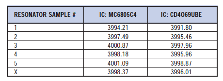
From this data, it is possible to predict that the standard ZTA4.00MG resonator will have an approximate +0.06% frequency shift from the original 4.00MHz +0.5% initial tolerance. This is of course a negligible shift and will not affect circuit performance in any way.
Circuits for Various IC/LSI:
Ceramic resonators are being used in a wide range of applications in combination with various kinds of IC’s by making good use of the previously mentioned features. The following are a few examples of acutal applications.
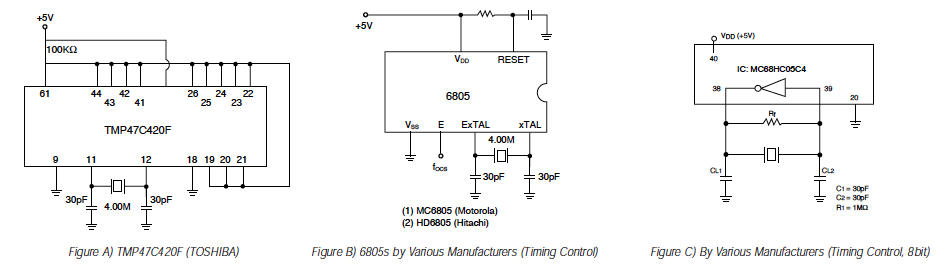
Applications of Microprocessors: Ceramic resonators are optimum as a stable oscillating element for various kinds of microprocessors: 4 bit, 8 bit, and 16 bit. As the general frequency tolerance required for the reference clock of microprocessors is +2% – 3%, standard units meet this requirement. Ask your ECS or LSI manufacturers about circuit constants because they vary with frequency and the LSI circuit being used. Fig.A shows an application with a 4 bit microprocessor, and Fig.B shows an application with an 8 bit microprocessor.
Remote Control IC: Remote controls have increasingly become a common feature. Oscillation frequency is normally 400-500 KHz, with 455KHz being the most popular. This 455KHz is divided by a carrier signal generator so that approximately 38KHz of carrier is generated.
VCO (Voltage Controlled Oscillator) Circuits: VCO circuits are used in TV’s and audio equipment because the signals need to be processed in synchronization with pilot signals transmitted from broadcasting stations. Oscillation circuits, such as LC and RC were originally used; however, ceramic resonators are now used since they require no adjustment and have superior stability over the older type of circuits. Resonators for VCO applications are required to have a wide variable frequency.
Miscellaneous: Other than the above mentioned uses, ceramic resonators are widely used with IC’s for voice synthesis and clock generation. For general timing control applications, oscillation frequency is usually selected by the user based on the IC manufacturer’s recommended operating frequency range. The selection of this frequency with a given IC will dictate what circuit values and which ceramic resonator will be appropriate. Please contact your local ECS sales representative when selecting a ceramic resonator part number. As mentioned earlier, there are many applications for ceramic resonators. Some of the more application specific oscillator circuits require that unique ceramic resonators be developed for that application and IC.
Oscillation Rise Time
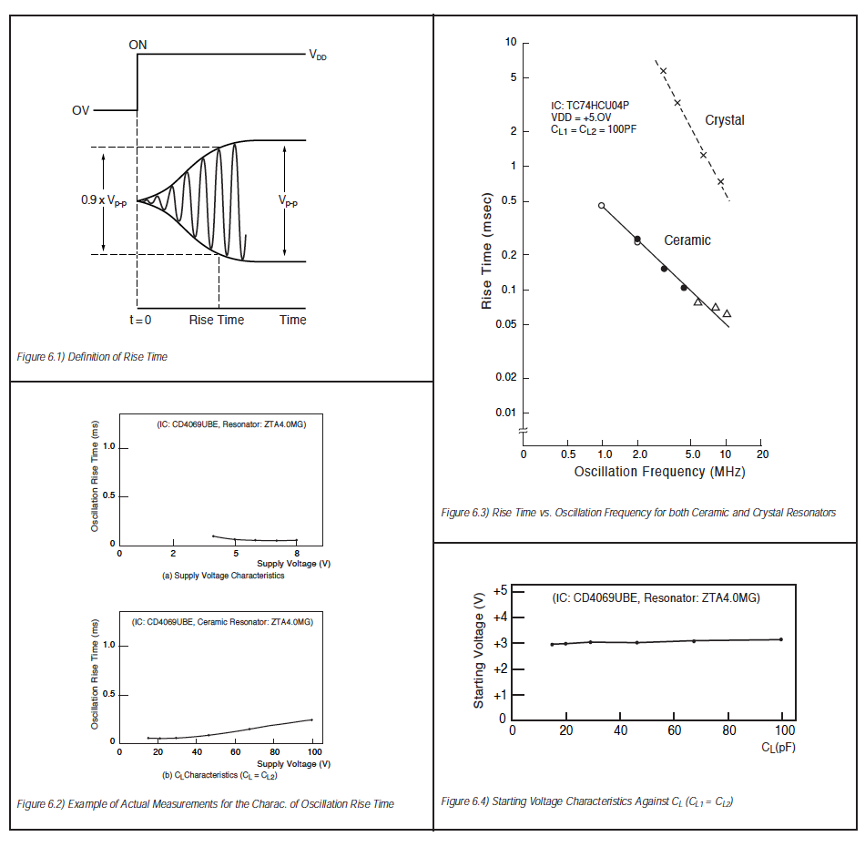
Oscillation rise time means the time when oscillation develops from a transient area to a steady area at the time the power to the IC is activated. WIth a ceramic resonator, it is defined as the time to reach 90% of the oscillation level under steady conditions as shown in Fig.6.1. Rise time is primarily a function of oscillating circuit design. Generally, smaller loading capacitance, a higher frequency ceramic resonator, and a smaller size of ceramic resonator will cause a faster rise time. The effect of load capacitance becomes more apparent as the capacitance of the resonator decreases. Fig6.2 shows an actual measurement of rise time against load capacitance (CL) and supply voltage. It is noteworthy that the rise time is one or two decades faster for a ceramic resonator than for a quartz crystal. (This point is graphically illustrated in Fig.6.3)
Starting Voltage: Starting voltage means the minimum supply voltage at which an oscillating circuit can operate. Starting voltage is affected by all circuit elements. It is determined mostly by the characteristics of the IC. Fig.6.4 shows an example of an actual measurement for the starting voltage characteristics against the loading capacitance.
CHARACTERISTICS OF CERAMIC RESONATOR OSCILLATION
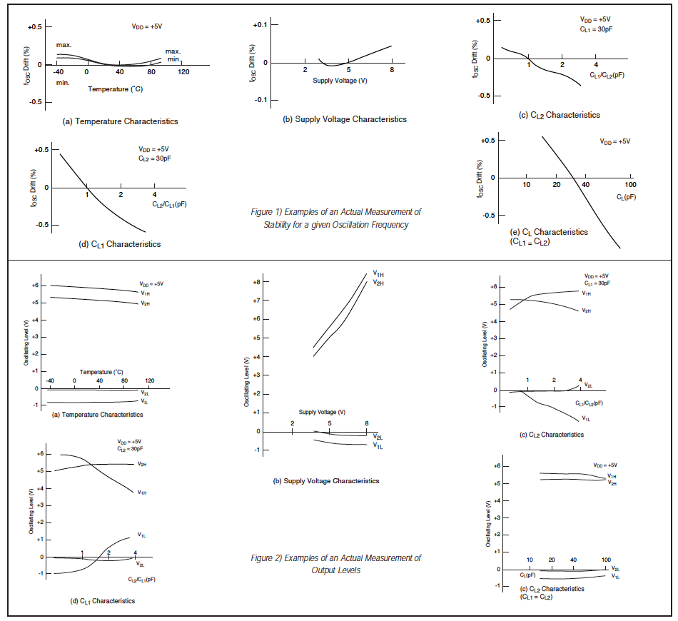
The following describes the general characteristics of oscillation in the basic circuit. Contact ECS International for detailed characteristics of oscillation with specific kinds of IC’s and LSI’s. The stability against temperature change ia +0.3 to 0.5% within a range of -20 C to +80 C, although it varies slightly depending on the ceramic material. Influences of load capacitance (CL1, CL2) on the oscillation frequency is relatively high as can be calculated from the formula for fosc. The fosc varies by approximately + 0.1% because of the capacitance deviation of +0.1% in the working voltage range. The fosc also varies with the characteristics of the IC.
Supply Voltage Variation Characteristics: See Fig.1 below for an example of an actual measurement of stability for a given oscillation frequency.
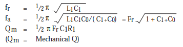
Oscillation Level: Below are examples of actual measurements of the oscillation level against temperature, supply voltage, and load capacitance (CL1, CL2). The oscillating level is required to be stable over a wide temperature range, and temperature characteristics be as flat as possible. This change is linear with supply voltage unless the IC has an internal constant voltage power source.