
Written by David Meaney, Vice President of Global Technical Sales and Marketing at ECS Inc. International
For engineers that are working on digital designs, this note and associated video should reacquaint you with crystal oscillator timing theory and some practical aspects of circuit design. These theories of quartz crystal design are easily applicable to many applications.
Choosing a Parallel or Series Resonant Crystal
When trying to find the best solution for clocking your application, it can be confusing whether a particular circuit arrangement requires a parallel or series resonant crystal. This can be difficult because there is no difference in the construction of a series resonant crystal and parallel resonant crystal because they are manufactured using the exact same process. The difference between them is that the resonant frequency of a parallel resonant crystal is slightly higher than a series resonant crystal. It is important to have two different modes of resonance because they are optimized to the design of the oscillator circuit.
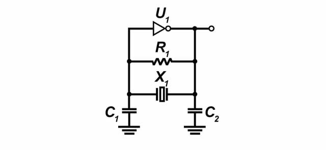
A Pierce oscillator design, as shown below, is optimized to use a series resonant crystal.
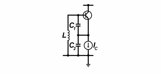
A Colpitts oscillator design, as shown below, is optimized to use a parallel resonant crystal.
Because the two crystals are identical when they come off the assembly line, the differences come from application and usage. Because a crystal is a complex piezoelectric device that has a characteristic operating curve which has two points of resonance. The fs point is where the frequency is minimal, the impedance is purely resistive, and where the crystal draws the most current. The anti-resonance point is almost exclusively inductive or capacitive. It is at this point when the crystal’s frequency is at a maximum and the current flow is at a minimum.

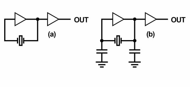
The area between fs and anti-resonance is called the area of usual parallel resonance. This is where most oscillator circuits will operate. Parallel resonance is accomplished by incorporating a small amount of capacitance into the circuit known as the load capacitance. This capacitance is put directly across the crystal terminals to achieve the desired operating frequency by forcing the crystal to resonate around usual parallel resonance. A greatly simplified diagram of a series resonant and parallel resonant oscillator is shown below.
Crystal Functionality in an Electrically Equivalent Circuit
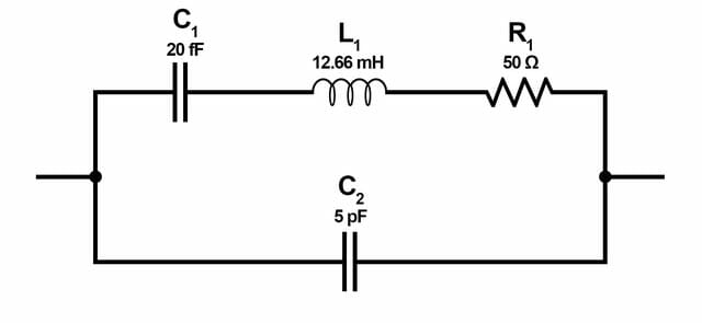
The circuit above is the electrical model of a quartz crystal, which is used in oscillators. The equivalent electrical circuit shows a series RLC circuit in parallel with a capacitance, C2. The equivalent impedance has a series resonance where C1 resonates with inductance, L1, at the crystal’s operating frequency. This is the crystal’s series frequency. There is a second frequency point established as a result of the parallel resonance created when L1 and C1 resonates with the parallel shunt capacitor at C2 as shown.
Load Capacitance
The value of a load capacitor varies between 12 pF and 32 pF depending on the crystal. This will be listed on the manufacturer’s datasheet under CL for the frequency specified. There are other factors to be considered such as trace impedance and stray capacitance. This graph illustrates the change in frequency (in parts per million) in relationship to load capacitance values.
For more information on load capacitance, watch this short video.
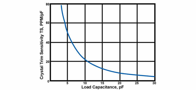
If the goal is a stable, fixed frequency oscillator, choose a crystal designed to use a large load capacitance value like 18 pF – 20 pF. To tune, or pull, the crystal, or need a low power solution, choose a crystal that uses a small load capacitance value like 8 pF – 12 pF.
For a more detailed explanation of series versus parallel circuit design and usage, watch our accompanying video here.
For ECS Inc. International’s crystal listings, click here.
For ECS Inc. International’s latest product catalog, click here.
For additional ECS Inc. International technical guides, click here.
For additional video resources, click here.
Please contact us if you need additional information or have a specific requirement in your application.
ECS Inc. International
15351 West 109th Street
Lenexa, KS 66219
Tel: 913-782-7787
Toll Free: 1-800-237-1041
Fax: 913-782-6991